Newtons Bit
Penultimate Amazing
- Joined
- Apr 12, 2007
- Messages
- 10,049
Why did the columns bow in? There’s been quite a bit of speculation and misinformed opinion about the mechanics of the structure that caused that, so I hope to do a little bit of enlightenment. The first thing that needs to be looked at is the problem. Figure 1 shows a typical building section through a building such as the WTC towers.
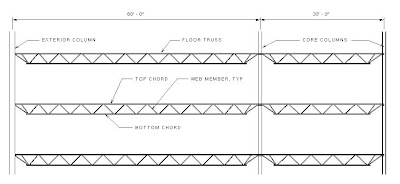
Figure 1
Everything here is fairly straight forward. The gravity load path can be seen very easily. The floor trusses deliver the vertical floor loads to the columns which deliver them to the foundations. But what happens when a core column is severed as in Figure 2?
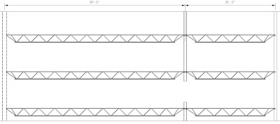
Figure 2
Things start to get a little bit more complicated. The first thing that should dawn on most people is that the floor is no longer being supported by the middle column which is going to cause some problems. The middle column will drop unless there is a force that can resist it, see Figure 3.

Figure 3
As the column drops, the top chord of the floor truss develops tensile forces (it is quite literally stretched). This tensile force has two parts, a vertical portion that pulls the column up and a horizontal force that pulls the rest of the structure in. This can be seen in Figure 4.
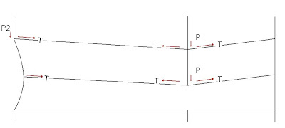
Figure 4
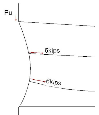
The other things to note here is that the left column is still under its full axial loading (P2, which will be important in the analysis). The left column is already shown pulled in to some degree, however it is not to scale. Further modifying the problem, we know that the fires caused the trusses to sag to some degree. If the fire is hot enough, the truss will become a tension only member. This means that the top chord of the truss will act something like a rope and pull inwards at its connections. This can be seen in Figure 5. There is another condition as well (which I have no illustrated) that will cause the heated floor to expand outwards without losing its bending capacity and thus not sagging. It is a condition that likely proceeded that of the sagging floor trusses.
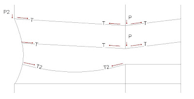
Figure 5
NIST (1-6D) estimates that the total pull-in force at the exterior columns is roughly 6 kips (6,000lbs) at each column. The truss to column connection consisted of (2) 5/8” diameter bolts. Even non-structural grade bolts of this size will have a shear capacity of over 5kips each, so it is reasonable to assume that the top chord of the truss will not pull off of the columns at the connections due to a 6kip load.
Is this 6 kips enough to pull the column in several feet as seen in the photos of the tower?

Math is needed here. First some assumptions need to be made. For the purpose of this analysis, let the exterior column be HSS14x14x5/16 tubes at 25% of the maximum axial load prior to any damage. The column has the following properties:
Similar to HSS 14x14x5/16
A = 15.7in^2
I = 739 in^4
S = 92.3 in ^3
Pn = 557k (from AISC LRFD 3rd, table 4-6 with an unbraced length, KL = 12’-4”)
Pu = ¼* 557k = 139k
Mn = 92.3in^3*46ksi = 4645 kip*in (Mn = maximum bending capacity)
The column itself will bend inwardly until it snaps if the column itself ever becomes inelastic. This can be defined by the ratio (I’ve simplified this a bit): Mu/Mn + Pu/Pn < 1. The other limit state is P-delta. When the exterior column is pulled inwards, it deflects. This deflection(Δ) generates a moment, specifically P2*Δ. This moment, creates more deflection, which further magnifies the moment, creating more moment, and so forth. P-delta has two outcomes: the moment reaches equilibrium at some point, or becomes unstable and continues to grow. This phenomenon can be easily shown with a simple experiment. Take a straw and try to compress it between your fingers. It has a surprising amount of strength. Now push the middle in slightly. This is p-delta.
We know that the floor diaphragm along the wall were greatly damaged due to fire and the impact of the aircraft. Let us assume that there are two floor diaphragms that are damaged to the point that they no longer provide bracing against buckling. There is thus a pull-in force of 6kips at two places along the length of the column.
CALCULATION 1: DIAPHRAGM DAMAGE, NO FIRE EFFECTS
Unbraced length = 37’-0”
Pu = 139k
Pn = 465k (from AISC LRFD 3rd, table 4-6 with an unbraced length, KL = 37’-0”)
Mn = 4645 kip*in
Mu = P*a
Mu = 6kip*1/3*37ft
Mu = 74kip*ft or 888 kip*in
Deflection = P*a *(3L^2 – 4*a^2)/(24*E*I) (Formula from AISC LRFD 3rd)
a = 1/3*L
= P * 1/3L *(3L^2 – 4/9*L^2)/(24*E*I)
= 23*P*L^3/(1296*E*I)
= 23*6k*(37ft*12in/ft)^3/(1296*29000ksi*739in)
= 0.435in
Additional moment due to P-delta
Mu+ = 0.435in*139k = 61.02 kip*in
Additional Deflection = Mu+*L^2 / (4*EI)
= 61.02kip*in*(37 * 12ft\in)^2 / (4*29000ksi*739in^3)
= 0.140in
Additional moment due to P-delta2
Mu++ = (0.435+0.140)in*139k = 79.93 kip*in
Additional Deflection = Mu++*L^2 / (4*EI)
= 79.93kip*in*(37 * 12ft\in)^2 / (4*29000ksi*739in^3)
= 0.184in
As seen, the first p-delta iteration results in an increased deflection of 0.140in. The second results in a deflection of only 0.184in. We can thus conclude that p-delta will eventually converge and that no further iterations are necessary. The 6kip pull-in force with no effect of fire will not result in the column becoming unstable.
In a 600C fire, the Modulus of Elasticity will have reduced to approximately 0.3 of its original value, and the yield strength to 0.5 of its original value. The effect of the Modulus of Elasticity being so greatly lowered is of far greater important than the yield strength, however.
CALCULATION 2: DIAPHRAGM DAMAGE, 500C FIRE
Unbraced length = 37’-0”
E = 0.3*29000ksi = 8700ksi
Pu = 139k
Pn = 465k*0.5 = 233k
Mn = 4645 kip*in *0.5 = 2323kip*in
Mu = P*a
Mu = 6kip*1/3*37ft
Mu = 74kip*ft or 888 kip*in
Deflection = P*a *(3L^2 – 4*a^2)/(24*E*I) (Formula from AISC LRFD 3rd)
a = 1/3*L
= P * 1/3L *(3L^2 – 4/9*L^2)/(24*E*I)
= 23*P*L^3/(1296*E*I)
= 23*6k*(37ft*12in/ft)^3/(1296*8700ksi*739in)
= 1.45in
Additional moment due to P-delta
Mu+ = 1.45in*139k = 201.6 kip*in
Additional Deflection = Mu+*L^2 / (4*EI)
= 201.6kip*in*(37 * 12ft\in)^2 / (4*8700ksi*739in^3)
= 1.55in
Additional moment due to P-delta2
Mu++ = (1.45+1.55)in*139k = 417 kip*in
Additional Deflection = Mu++*L^2 / (4*EI)
= 417kip*in*(37 * 12ft\in)^2 / (4*8700ksi*739in^3)
= 3.20in
This results in the column becoming unstable due to p-delta. This can easily be seen in that the deflection due to P-delta2 is double that of P-delta1. It can therefore be concluded that it was necessary for both fire and damage to result in the collapse of the towers.
Edit: Apologies for the terrible formatting.
Figure 1
Everything here is fairly straight forward. The gravity load path can be seen very easily. The floor trusses deliver the vertical floor loads to the columns which deliver them to the foundations. But what happens when a core column is severed as in Figure 2?
Figure 2
Figure 3
As the column drops, the top chord of the floor truss develops tensile forces (it is quite literally stretched). This tensile force has two parts, a vertical portion that pulls the column up and a horizontal force that pulls the rest of the structure in. This can be seen in Figure 4.
Figure 4
The other things to note here is that the left column is still under its full axial loading (P2, which will be important in the analysis). The left column is already shown pulled in to some degree, however it is not to scale. Further modifying the problem, we know that the fires caused the trusses to sag to some degree. If the fire is hot enough, the truss will become a tension only member. This means that the top chord of the truss will act something like a rope and pull inwards at its connections. This can be seen in Figure 5. There is another condition as well (which I have no illustrated) that will cause the heated floor to expand outwards without losing its bending capacity and thus not sagging. It is a condition that likely proceeded that of the sagging floor trusses.
Figure 5
NIST (1-6D) estimates that the total pull-in force at the exterior columns is roughly 6 kips (6,000lbs) at each column. The truss to column connection consisted of (2) 5/8” diameter bolts. Even non-structural grade bolts of this size will have a shear capacity of over 5kips each, so it is reasonable to assume that the top chord of the truss will not pull off of the columns at the connections due to a 6kip load.
Is this 6 kips enough to pull the column in several feet as seen in the photos of the tower?
Math is needed here. First some assumptions need to be made. For the purpose of this analysis, let the exterior column be HSS14x14x5/16 tubes at 25% of the maximum axial load prior to any damage. The column has the following properties:
Similar to HSS 14x14x5/16
A = 15.7in^2
I = 739 in^4
S = 92.3 in ^3
Pn = 557k (from AISC LRFD 3rd, table 4-6 with an unbraced length, KL = 12’-4”)
Pu = ¼* 557k = 139k
Mn = 92.3in^3*46ksi = 4645 kip*in (Mn = maximum bending capacity)
The column itself will bend inwardly until it snaps if the column itself ever becomes inelastic. This can be defined by the ratio (I’ve simplified this a bit): Mu/Mn + Pu/Pn < 1. The other limit state is P-delta. When the exterior column is pulled inwards, it deflects. This deflection(Δ) generates a moment, specifically P2*Δ. This moment, creates more deflection, which further magnifies the moment, creating more moment, and so forth. P-delta has two outcomes: the moment reaches equilibrium at some point, or becomes unstable and continues to grow. This phenomenon can be easily shown with a simple experiment. Take a straw and try to compress it between your fingers. It has a surprising amount of strength. Now push the middle in slightly. This is p-delta.
We know that the floor diaphragm along the wall were greatly damaged due to fire and the impact of the aircraft. Let us assume that there are two floor diaphragms that are damaged to the point that they no longer provide bracing against buckling. There is thus a pull-in force of 6kips at two places along the length of the column.
Unbraced length = 37’-0”
Pu = 139k
Pn = 465k (from AISC LRFD 3rd, table 4-6 with an unbraced length, KL = 37’-0”)
Mn = 4645 kip*in
Mu = P*a
Mu = 6kip*1/3*37ft
Mu = 74kip*ft or 888 kip*in
Deflection = P*a *(3L^2 – 4*a^2)/(24*E*I) (Formula from AISC LRFD 3rd)
a = 1/3*L
= P * 1/3L *(3L^2 – 4/9*L^2)/(24*E*I)
= 23*P*L^3/(1296*E*I)
= 23*6k*(37ft*12in/ft)^3/(1296*29000ksi*739in)
= 0.435in
Additional moment due to P-delta
Mu+ = 0.435in*139k = 61.02 kip*in
Additional Deflection = Mu+*L^2 / (4*EI)
= 61.02kip*in*(37 * 12ft\in)^2 / (4*29000ksi*739in^3)
= 0.140in
Additional moment due to P-delta2
Mu++ = (0.435+0.140)in*139k = 79.93 kip*in
Additional Deflection = Mu++*L^2 / (4*EI)
= 79.93kip*in*(37 * 12ft\in)^2 / (4*29000ksi*739in^3)
= 0.184in
As seen, the first p-delta iteration results in an increased deflection of 0.140in. The second results in a deflection of only 0.184in. We can thus conclude that p-delta will eventually converge and that no further iterations are necessary. The 6kip pull-in force with no effect of fire will not result in the column becoming unstable.
In a 600C fire, the Modulus of Elasticity will have reduced to approximately 0.3 of its original value, and the yield strength to 0.5 of its original value. The effect of the Modulus of Elasticity being so greatly lowered is of far greater important than the yield strength, however.
CALCULATION 2: DIAPHRAGM DAMAGE, 500C FIRE
Unbraced length = 37’-0”
E = 0.3*29000ksi = 8700ksi
Pu = 139k
Pn = 465k*0.5 = 233k
Mn = 4645 kip*in *0.5 = 2323kip*in
Mu = P*a
Mu = 6kip*1/3*37ft
Mu = 74kip*ft or 888 kip*in
Deflection = P*a *(3L^2 – 4*a^2)/(24*E*I) (Formula from AISC LRFD 3rd)
a = 1/3*L
= P * 1/3L *(3L^2 – 4/9*L^2)/(24*E*I)
= 23*P*L^3/(1296*E*I)
= 23*6k*(37ft*12in/ft)^3/(1296*8700ksi*739in)
= 1.45in
Additional moment due to P-delta
Mu+ = 1.45in*139k = 201.6 kip*in
Additional Deflection = Mu+*L^2 / (4*EI)
= 201.6kip*in*(37 * 12ft\in)^2 / (4*8700ksi*739in^3)
= 1.55in
Additional moment due to P-delta2
Mu++ = (1.45+1.55)in*139k = 417 kip*in
Additional Deflection = Mu++*L^2 / (4*EI)
= 417kip*in*(37 * 12ft\in)^2 / (4*8700ksi*739in^3)
= 3.20in
This results in the column becoming unstable due to p-delta. This can easily be seen in that the deflection due to P-delta2 is double that of P-delta1. It can therefore be concluded that it was necessary for both fire and damage to result in the collapse of the towers.
Edit: Apologies for the terrible formatting.
Last edited:

")